Choosing the right Cnc Milling Cutter affects accuracy, tool life, surface finish, and production cost. Buyers often focus on price first. That can be a costly mistake.
This guide examines the Top 10 Types of CNC Milling Cutters for Buyers. It compares end mills, face mills, ball nose cutters, roughing cutters, slot drills, chamfer mills, and specialty designs. Each cutter serves a different machining need. Material matters. Aluminum may require polished flutes and open chip spaces. Hardened steel often demands tougher carbide, suitable coatings, and controlled cutting speeds. A cutter that performs well on aluminum can fail quickly in stainless steel.
Tony Schmitz, a respected machining researcher and professor, has stated, “The machine tool, cutting tool, and workpiece form a dynamic system.” His point remains practical. Cutter selection cannot be separated from spindle power, holder accuracy, workholding, and machine rigidity. Even a premium Cnc Milling Cutter may chatter on a weak setup. Small details matter.
This overview uses application-based guidance rather than catalogue language. It considers flute count, helix angle, diameter, coating, runout, coolant access, and expected tool life. Real workshop experience also shows that manufacturer data is only a starting point. Actual results can vary. That is worth remembering.
Some choices remain imperfect. Testing is necessary. Buyers should compare trial cuts, inspect chips, measure surface quality, and record tool wear. The most expensive cutter is not always the best cutter. The most economical choice may reduce downtime, scrap, and repeated setup adjustments.
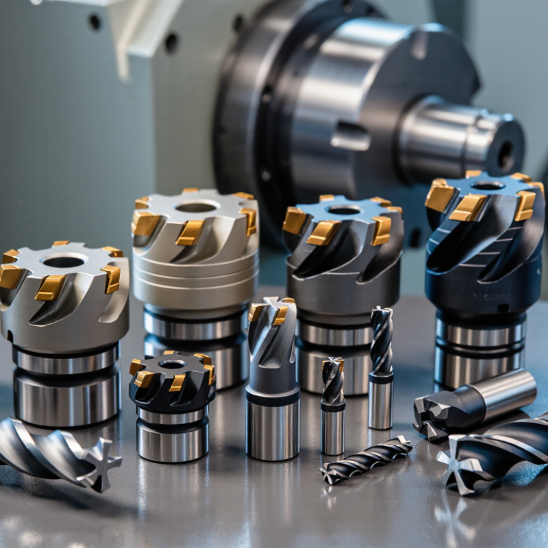
Choosing among the top 10 CNC milling cutter types starts with three details: flutes, helix angle, and runout. These factors influence cutting force, chip evacuation, surface finish, and tool life. Common choices include end mills, ball nose cutters, face mills, slot drills, roughing cutters, chamfer mills, thread mills, drill mills, T-slot cutters, and fly cutters.
Flute count changes how a cutter behaves. Two-flute tools leave more space for chips, especially in aluminum and deep slots. Three or four flutes often provide better rigidity for steel and general profiling. More flutes are not automatically better. A crowded flute pattern can trap chips. I have seen this mistake during high-feed trials.
Helix angles also deserve careful attention. A higher helix can reduce cutting shock and improve finish, but it may increase axial pulling force. Lower helix designs can offer steadier control in harder materials. The best angle depends on material, depth, coolant, and machine rigidity. Small differences matter.
Runout below 10 μm is a practical target for precision work. Measure the assembled tool, not only the cutter. A dirty holder, damaged collet, or uneven tightening can destroy that result. Check runout near the cutting edge with a suitable gauge. Even a well-made cutter cannot correct poor setup. I still recheck after tool changes, because assumptions are cheaper to question than finished parts.
Match cutter geometry with the material and operation. Face mills create broad, flat surfaces. End mills cut slots, pockets, and profiles. No cutter wins every job.
Roughing end mills use serrated edges for faster stock removal. Slab mills also remove material across large horizontal areas. Check machine power and rigidity.
Ball nose cutters suit smooth three-dimensional contours. They often work well on hardened molds. Use controlled passes to protect surface quality.
Bull nose cutters combine stronger corners with controlled finishing. They can reduce corner damage during profile work. Results still depend on setup stability.
Chip load is material removed by each tooth per revolution. Calculate it as feed rate divided by spindle speed and flute count. Start conservatively.
Radial engagement describes how deeply the cutter enters the material sideways. A practical starting range is 5–15% of cutter diameter. Full engagement creates more heat.
Larger cutters resist deflection but may not reach narrow corners. Smaller cutters reach details but need shorter projection. A 12 mm cutter extending 18 mm is usually steadier than a 6 mm cutter extending 30 mm.
No coating solves every application. A coating suited to steel may perform poorly on aluminum. Check workpiece material, coolant, and cutting temperature.
Check runout, holder rigidity, coolant delivery, and actual chip load. Watch chip color and tool wear. Shiny chips may indicate rubbing. Blue chips may signal excessive heat.
Cutting charts are only starting points. Real machines behave differently. Record diameter, flutes, speed, feed, step-over, tool life, and surface finish. A chart can be right. The setup can still fail.
Choosing the right Cnc Milling Cutter requires more than comparing price or diameter. This guide explains essential fundamentals, including flute count, helix angle, and the importance of keeping tool runout below 10 μm for accuracy and consistent surface quality. It also introduces ten major cutter types classified by geometry and milling operation, helping buyers match tool design with slotting, profiling, roughing, finishing, drilling, or specialized machining tasks.
The article compares carbide and HSS cutters by cutting speed, hardness, heat resistance, and expected tool life. It also presents practical selection guidance based on chip load, radial engagement, cutter diameter, workpiece material, and machine limitations. Additional factors such as coatings, dimensional tolerances, tool rigidity, spindle capability, coolant use, and overall cutting conditions are considered. By evaluating these details together, buyers can select a cutter that balances productivity, precision, durability, and operating cost for their specific CNC milling requirements.

 N&D Carbide