Choosing the right Spiral End Mill is not a catalog exercise. It is a machining decision shaped by material, machine power, toolholding, and production goals. A cutter that performs beautifully in aluminum may struggle in stainless steel. The sound changes first. Chips become hot, edges wear, and the surface loses its clean reflection.
In the shop, I compare flute geometry, helix angle, diameter, coating, and corner design before ordering. A three-flute tool can evacuate chips effectively in aluminum, especially at higher feed rates. A four-flute option may provide better rigidity and finish in steel. However, flute count alone never guarantees success. Runout, coolant delivery, workholding, and spindle condition can overturn a promising selection. Results vary.
Reliable guidance begins with the workpiece and ends with measured results. Check the manufacturer’s cutting data, then adjust speeds and feeds gradually. Watch chip shape, spindle load, vibration, and edge color during a controlled test cut. Small details matter. A polished flute may reduce aluminum adhesion, while a TiAlN coating can support hotter cutting in suitable steels. These choices require technical judgment, not guesswork.
There is no universal best tool. Even experienced machinists occasionally choose too aggressively, especially when chasing cycle-time reductions. That mistake can be useful if the evidence is recorded. This guide explains how to select a Spiral End Mill with practical reasoning, realistic limits, and enough flexibility for actual shop conditions.
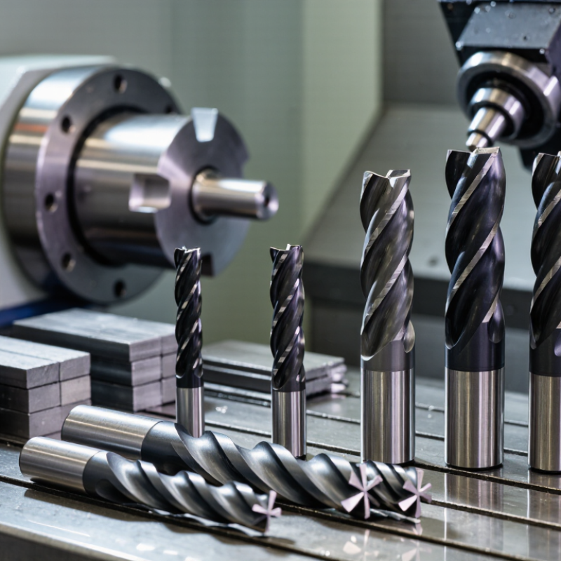
Spiral end mills remove material through rotating, helical cutting edges. Their helix angle controls chip flow, cutting pressure, and surface quality. A 30-degree helix is a practical general-purpose choice for many steels and aluminum alloys. Higher helix angles, often 40 to 45 degrees, improve shearing and finish in softer materials. They can also pull the workpiece upward, which demands secure fixturing.
Diameter, flute count, coating, and core thickness must match the operation. Two-flute tools leave more space for chips during aluminum slotting. Four-flute tools usually provide better rigidity and finish in steel. The U.S. Cutting Tool Institute and the Association for Manufacturing Technology reported United States cutting-tool consumption near 2.6 billion dollars in 2024. That scale reflects a competitive market, but it does not make every design suitable for every machine. A rigid tool in a weak setup may still chatter.
Tips: Check the manufacturer’s chip-load chart, then reduce feed by 10 to 20 percent during the first test. Watch chip shape, spindle load, and edge wear. ISO 13399 supports consistent tool-data communication, yet real cutting conditions remain imperfect. Coolant direction, runout, and fixture stiffness can change the result. I would not select a spiral end mill from helix angle alone. Trial cuts still reveal what the catalog cannot.
How to Choose the Right Spiral End Mill?
Match the End Mill to the Workpiece Material
The workpiece material should guide your end mill choice before cutting speed does. Aluminum usually benefits from a sharp, polished flute and a higher helix angle. These features help lift chips from soft, sticky material. Fewer flutes can also create more chip space. Keep the tool clean. Built-up material can quickly ruin the surface finish.
Steel demands a different approach. A rigid carbide end mill, moderate helix, and suitable coating can improve tool life. Stainless steel needs special care because it work-hardens under rubbing. Use a sharp cutting edge, steady feed, and enough coolant or air to clear chips. Do not let the tool dwell. That small mistake can create heat and harden the cut.
Plastics require sharp edges and low heat. Polished flutes reduce melting and prevent chips from welding inside the gullets. Cast iron often favors a strong edge and controlled chip evacuation. Its abrasive dust may also affect machine cleanliness. I have found that selection charts are useful, but they are only starting points. Machine rigidity, tool overhang, workholding, and actual material hardness can change the result. A tool that works well in one workshop may perform poorly on another machine. Check cutting data, test a small area, and inspect the chips before increasing the load.
Flute count controls chip space, feed potential, and surface quality. For aluminum or other soft materials, two or three flutes often leave enough room for chips. Four or more flutes can improve finish in steel, especially during light finishing cuts. More flutes are not automatically better. Packed chips can quickly damage the tool and workpiece.
Helix angle changes how the cutter enters and exits the material. A 30-degree helix suits many general milling operations. A higher helix, around 40 to 45 degrees, can shear soft materials smoothly and lift chips from the slot. However, it may pull thin workpieces upward. Lower helix angles can feel steadier in harder materials, but chip removal may suffer. Watch the cut.
Cutting diameter affects rigidity, reach, and material removal. Choose the largest diameter that fits the pocket or corner radius. A larger tool usually deflects less, producing a straighter wall. Long reach changes the decision. I once selected a small cutter for easy access, then saw visible chatter on a shallow pocket. The mistake was not the flute count alone; excessive stickout weakened the setup. Check tool projection, workholding, spindle power, and actual chip evacuation before changing speeds. Test cuts still matter, because the ideal combination on paper may behave differently on your machine.
Choosing the right spiral end mill is only half the job. Cutting parameters decide whether it cuts cleanly or rubs against the workpiece. The International Energy Agency’s 2023 Energy Technology Perspectives reports that industry uses roughly 37% of global final energy. Efficient machining matters.
Start with surface speed, chip load, and engagement. Use these formulas: RPM = (cutting speed × 1,000) ÷ (π × tool diameter), and feed rate = RPM × flute count × chip load. For a 10 mm, two-flute carbide tool cutting aluminum, a practical trial may use 250 m/min and 0.05 mm chip load. That produces about 7,960 RPM and 796 mm/min feed. Reduce both values when the machine lacks rigidity.
Radial engagement changes everything. A 10% stepover allows higher speed than a 50% stepover. Axial depth should also match tool diameter, coolant access, and workholding strength. The U.S. Department of Energy’s 2022 Industrial Decarbonization Roadmap links process efficiency with lower energy demand, but faster is not always better. Listen for a sharp, steady cut. A high-pitched squeal often signals rubbing or excessive speed. Dark chips suggest heat. I sometimes reduce feed too quickly, which can worsen rubbing; that mistake deserves checking before blaming the end mill. Record spindle load, chip color, and edge wear after each trial.
The chart shows practical starting values for cutting speed when using a carbide spiral end mill approximately 6 mm in diameter for general milling. Aluminum permits the highest cutting speed, while stainless steel and titanium require lower speeds because of their higher heat generation and work-hardening behavior. Adjust speed, feed per tooth, axial depth, and radial engagement according to tool geometry, machine rigidity, coolant, and chip evacuation.
Choosing the right spiral end mill starts with the workpiece, not the catalog page. For aluminum, a polished flute and high helix can evacuate chips quickly. For stainless steel, a tougher substrate and moderate helix reduce edge chipping. A TiAlN-type coating suits hot, dry cutting, while a smoother coating may reduce aluminum adhesion. Coating selection is not universal. It depends on heat, speed, coolant, and chip control.
Geometry must match the cut. Two flutes leave more room for chips in deep aluminum pockets. Three or four flutes often improve finish and rigidity in steel. A variable-pitch design can reduce harmonic marks, especially during side milling. Check the tool’s recommended radial and axial engagement. ISO 8688-2 defines tool-life testing methods, but shop results still vary with machine stiffness and workholding. That gap matters.
Application data should guide the final choice. The U.S. Department of Energy reports that metalworking fluids can represent roughly 7–17% of manufacturing costs, making dry or minimum-quantity lubrication trials financially relevant. DOE energy-efficiency guidance also links excessive cutting resistance with higher power demand. Start with the manufacturer’s cutting range, then test one variable at a time. I have seen a harder coating fail early when run too slowly. More hardness was not the answer. A short tool-life trial, measured by flank wear, surface finish, and spindle load, is more reliable than appearance alone.
Choose the material first. Aluminum benefits from sharp edges, polished flutes, and higher helix angles. Steel needs rigidity and controlled cutting. Stainless steel needs steady feed and cooling. Plastics require low heat. Cast iron needs strong edges and clean chip evacuation.
Two or three flutes usually provide better chip space. This helps clear chips from deep pockets. Fewer flutes can reduce chip packing. Keep the tool clean.
Four or more flutes can improve finish and rigidity in steel. They work well during light finishing cuts. However, more flutes are not always better. Packed chips can damage both surfaces.
A 30-degree helix suits many general operations. A 40- to 45-degree helix can shear aluminum smoothly. It may lift thin workpieces. Lower helix angles can feel steadier in harder materials.
Choose the largest diameter that fits the pocket or corner radius. Larger tools usually deflect less. They can produce straighter walls. Long reach changes the decision. Excessive stickout can create chatter.
Coating choice depends on heat, speed, coolant, and chip control. Tougher substrates can support stainless steel cutting. Smoother surfaces may reduce aluminum adhesion. Variable-pitch geometry can reduce harmonic marks during side milling.
Check machine rigidity, workholding, spindle power, and tool projection. Inspect the chips and machined surface. Test a small area first. Paper data is only a starting point.
Change one variable at a time. Measure flank wear, surface finish, and spindle load. Watch for melting, built-up material, or chatter. I once blamed flute count, but excessive stickout caused the problem. That mistake still matters.
Choosing the right Spiral End Mill begins with understanding its basic design, including flute shape, cutting diameter, helix angle, and overall geometry. The best choice depends largely on the workpiece material, since aluminum, steel, stainless steel, plastics, and other materials require different approaches to chip evacuation, cutting pressure, and heat control. Flute count should match the machining goal: fewer flutes often provide more chip space, while more flutes can support faster feed rates and smoother finishing. The helix angle and diameter should also be selected according to the required surface quality, rigidity, and access to the workpiece.
Successful machining requires suitable cutting parameters, including spindle speed, feed rate, depth of cut, and coolant or air management. Coatings can improve wear resistance and heat performance, but their value depends on the material and application. By comparing tool geometry, coating options, machine capabilities, and production requirements, users can select a Spiral End Mill that delivers reliable tool life, efficient chip removal, accurate cutting, and consistent finished results.

N&D Carbide