Choosing Carbide Tipped Drill Bits For Metal is not simply a matter of selecting the hardest available tip. Metal type, thickness, drilling speed, coolant, and machine stability all influence the result. A bit that performs cleanly in cast iron may chatter badly in stainless steel. That difference appears quickly: overheated edges, blue chips, rough holes, or a cracked carbide tip.
Dr. Tony L. Schmitz, a respected machining researcher, has stated, “Machining is a system, not merely a cutting tool.” This principle is important when comparing carbide-tipped designs. The seven tips in this guide examine carbide grade, tip geometry, shank strength, coating, cutting parameters, coolant use, and supplier reliability. Each choice should match the actual workshop conditions, not only a catalog description. A rigid drill press, steady feed, and suitable coolant can extend tool life noticeably.
Still, no guide can replace a controlled test hole. That is the part many buyers overlook. Measure the hole diameter, inspect the edge, and watch for vibration after a few cuts. A cheaper drill may appear economical, yet repeated breakage can cost more than a premium option. Conversely, the most expensive bit is not automatically the best fit. Careful selection requires evidence, practical experience, and a willingness to reconsider the first choice. The details matter.
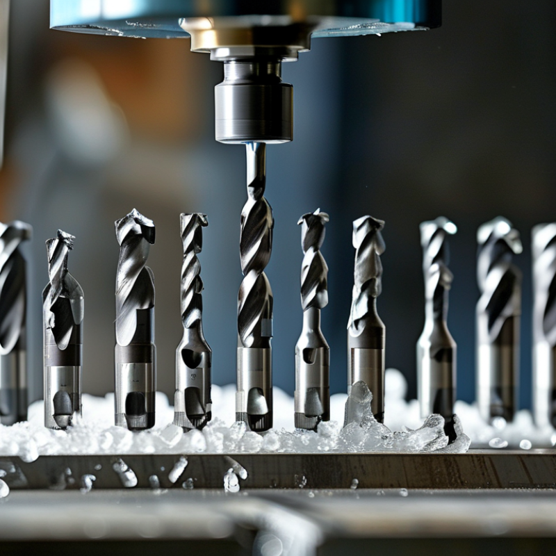
Understanding Carbide-Tipped Drill Bits for Metalworking
Carbide-tipped drill bits combine a tough steel body with a hard carbide cutting edge. This structure handles abrasive metals better than standard high-speed steel. The U.S. Geological Survey’s 2024 Mineral Commodity Summaries reports about 84,000 metric tons of tungsten mine production in 2023. Tungsten supports carbide hardness, but hardness alone does not guarantee performance. Geometry, brazing quality, cooling, and machine stability matter equally.
Tips: Choose a bit rated for your metal, not a universal model. Match the point angle to the material and required hole quality. Use a rigid machine with minimal runout. Apply cutting fluid when the manufacturer permits it. Keep feed pressure steady; rubbing creates heat quickly. Inspect the carbide edge after every difficult batch. Replace chipped tools early.
In practical metalworking, stainless steel often exposes weak choices first. A sharp carbide tip can produce clean chips, while a poor setup causes squealing and edge fracture. Industry cutting-tool guidance commonly emphasizes controlled speed, feed, and coolant selection because heat remains a primary failure factor. Yet calculations are only a starting point. I have seen a slower feed improve surface quality, then damage the edge through excessive rubbing. Measure the hole, inspect the chip color, and adjust one variable at a time. A bit that survives one alloy may fail quickly in another. Noise, vibration, and powdery chips deserve attention. They are not minor details.
7 Tips for Choosing Carbide-Tipped Drill Bits for Metal
Understanding Carbide-Tipped Drill Bits for Metalworking
The chart shows representative starting cutting speeds for carbide-tipped drills in common metals. Carbide generally supports higher cutting speeds than high-speed steel, but the correct value depends on drill diameter, workpiece hardness, machine rigidity, coolant, and hole depth. Use these figures as practical starting points and adjust gradually.
- Match the carbide grade and geometry to the workpiece material.
- Choose a point angle suited to the metal and hole requirements.
- Use a rigid machine setup to reduce chipping and vibration.
- Apply coolant or suitable lubrication when heat control is important.
- Set feed and speed according to drill diameter, not speed alone.
- Use split-point or self-centering geometry for improved hole accuracy.
- Inspect cutting edges regularly and replace damaged tools immediately.
Matching Drill Bit Geometry to Different Metal Types
7 Tips for Choosing Carbide Tipped Drill Bits for Metal
Matching Drill Bit Geometry to Different Metal Types
Tip 1: Check the point angle before drilling. Mild steel usually responds well to a 118-degree point. A 135-degree split point often reduces wandering in stainless steel. Tip 2: Choose a stronger web for hard metals. A thick web supports the cutting edges under heavy pressure. Tip 3: Match the helix to chip behavior. Aluminum benefits from a polished, high-helix flute that clears soft, sticky chips quickly.
Tip 4: Use a moderate helix for cast iron. Its short, abrasive chips need controlled evacuation, not aggressive lifting. Tip 5: Select a flatter rake for hardened steel. Too much rake can weaken the carbide edge. Tip 6: Consider edge preparation. A small honed edge survives interrupted cuts better, although it may cut less freely. Tip 7: Match the coating and coolant to the material. Stainless steel generates heat quickly, so steady feed and suitable coolant matter.
In workshop testing, I inspect the first hole, not just the product label. A clean entry, short chips, and stable sound usually indicate suitable geometry. A chart cannot predict every machine, clamp, or material batch. I have chosen the “correct” bit and still produced heat marks after using excessive speed. Carbide tips are hard, but they are not forgiving of vibration. Keep the workpiece rigid, clear chips often, and reduce speed when the edge shows discoloration. Small adjustments often outperform a supposedly perfect selection.
Selecting the Right Carbide Grade and Coating
Choosing the right carbide grade begins with the metal, not the drill’s appearance.
A tougher grade with more binder suits interrupted cuts, scale, and vibration. A harder grade resists wear when drilling abrasive cast iron or hardened steel. However, excessive hardness can make the edge chip under unstable conditions.
Start with the workpiece.
I once selected a wear-resistant grade for a rigid setup, then used it on a thin, flexible plate.
The cutting edge failed before the hole was complete. That mistake reinforced a practical rule:
match carbide toughness to machine stability.
For stainless steel, a sharp geometry and moderate toughness can reduce work hardening. For aluminum, polished flutes and a suitable coating help prevent built-up material.
Coating choice also depends on heat, friction, and chip evacuation.
A heat-resistant multilayer coating can support dry or high-temperature drilling in steel. A low-friction coating is often better for softer metals that tend to stick. Coatings cannot correct poor feeds, runout, or weak clamping.
Heat changes everything.
Check the manufacturer’s recommended cutting range, then test one hole while watching chip color and edge condition. A blue chip may signal excessive heat, while small edge fractures suggest impact or vibration. Coolant can help, but careless application may create thermal shock in carbide. That detail is easy to overlook. Record the grade, coating, speed, feed, and hole depth after testing, because small changes often explain large differences in tool life.
Choosing Bit Size, Shank Design, and Cutting Performance
Choosing Carbide Tipped Drill Bits for Metal
In a machine shop, bit size is rarely a casual choice. Measure the finished hole, not just the drawing. A 10 mm hole may require a slightly different tool when tolerance is tight. Match the bit diameter to the material and drilling depth. For thin sheet, a split point can reduce wandering. For thick steel, a rigid pilot hole may improve alignment, but it can also add setup time. Fit matters.
Shank design affects stability. A straight shank suits many standard chucks, while a reduced shank fits smaller machines without sacrificing a larger cutting diameter. Tri-flat shanks can limit slipping during heavy work. Keep the shank clean and fully seated. Even a small gap can create vibration. I have seen accurate bits produce poor holes because the chuck was worn. That mistake is easy to miss.
Cutting performance depends on more than carbide hardness. Choose flute geometry for the metal, hole depth, and available chip evacuation. Use steady feed pressure and suitable coolant when heat builds. Excessive speed can soften the cutting edge, while low feed can cause rubbing. Heat wins. Inspect the tip after each batch. Chips should exit cleanly, not pack inside the flutes. A small edge chip may still drill, but it often leaves a rough, oversized hole. I sometimes replace a bit too late, and that costs more than the tool.
Evaluating Work Conditions, Tool Life, and Safety Requirements
Choosing carbide tipped drill bits for metal starts with the work conditions, not the catalog description. The perfect bit does not exist. Match the carbide grade and geometry to the metal’s hardness, thickness, and heat sensitivity. Stainless steel needs controlled cutting heat, while cast iron produces abrasive dust and interrupted loading. Check spindle rigidity, runout, hole depth, and whether the cut enters a curved or uneven surface. A rigid setup usually extends tool life more than simply increasing hardness.
Tool life depends on speed, feed, coolant delivery, and chip evacuation. Excessive speed can create a bright heat band and edge chipping within seconds. Too little feed may rub instead of cut. Inspect the tip after every batch, especially when holes become oversized or chips change color. A practical mistake is judging life only by the number of holes. Production data should include cycle time, rejected holes, and replacement cost. Cutting tests should follow recognized procedures, but shop conditions rarely match laboratory results perfectly.
Safety requirements deserve equal attention. The U.S. Bureau of Labor Statistics recorded 888,220 private-industry injuries involving days away from work in 2023, showing why routine operations still need control. Use guarding, eye protection, secure workholding, and chip shields. Keep hands away from rotating tools, and avoid loose clothing. NIOSH recommends limiting occupational noise exposure to 85 dBA over eight hours, using a 3 dB exchange rate. Carbide can fracture without warning. Reduce vibration, replace damaged bits, and reconsider the setup when unusual noise appears.
Conclusion
Choosing the right Carbide Tipped Drill Bits For Metal requires more than selecting a sharp cutting tool. Start by understanding how carbide tips improve wear resistance, heat tolerance, and drilling stability in demanding metalworking applications. Match the bit’s geometry, point angle, flute design, and cutting edge to the material being drilled, since softer metals, hardened alloys, and abrasive materials each require different approaches. The correct carbide grade and coating can further improve durability, reduce friction, and support consistent chip removal.
Size, shank design, and cutting performance are equally important. Select a diameter that suits the hole specification and a shank that fits the machine securely while minimizing vibration. Before drilling, evaluate workpiece thickness, machine power, speed, feed rate, cooling, and chip evacuation. These conditions directly affect tool life, hole accuracy, and surface quality. Finally, follow appropriate safety practices, inspect bits regularly for wear or damage, and replace tools when performance declines to maintain efficient and reliable metalworking results.

 N&D Carbide